On-Die Power Rail Measurements: Setup and Best Practices
Accurate on-die power rail measurements depend on proper sense-line design, differential probing, and careful test setup at the package level.
Accurate on-die power rail measurements depend on proper sense-line design, differential probing, and careful test setup at the package level.

Transmission line losses—driven by skin effect and dielectric properties—play a critical role in degrading high-speed signal integrity and eye performance.
Transmission line loss directly affects eye diagram quality, with around −12 dB at Nyquist marking the limit before signal integrity rapidly degrades without equalization.
Three-phase AC voltages consist of three balanced sinusoidal vectors separated by 120°, with measurable differences between line-to-line and line-to-neutral values.


In a previous post, we briefly covered the basics of single- and three-phase AC power systems. Single-phase systems, as we've noted, comprise a single voltage vector with a magnitude (in VAC) and a phase angle. Of course, a three-phase voltage consists of three voltage vectors and three phase angles. This installment will go on to describe three-phase AC voltages in similarly brief fashion.
As mentioned above, three-phase AC sinusoidal voltages consist of three voltage vectors (Figure 1). By definition, these vectors are "balanced," being separated by 120° in phase, and being of equal magnitude. Moreover, the sum of all three voltages is equal to zero volts at the central neutral point.
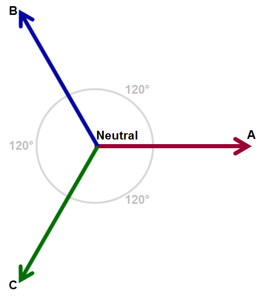
Typically, the three phases are designated A, B, and C. However, you may see other conventions used for these designations, such as 1, 2, and 3; L1, L2, and L3; and R, S, and T.
Like single-phase voltages, three-phase AC voltage vectors rotate at a given frequency, which typically is 50 or 60 Hz for utility-supplied voltages. As they rotate together, the vectors maintain their 120° phase separation (Figure 2). The voltage is generated by the utility using a rotating machine, i.e., a "generator." The generator uses a rotating magnetic field to induce a voltage in its stator. And again, like single-phase voltages, the resulting voltage vectors have magnitude and phase values.
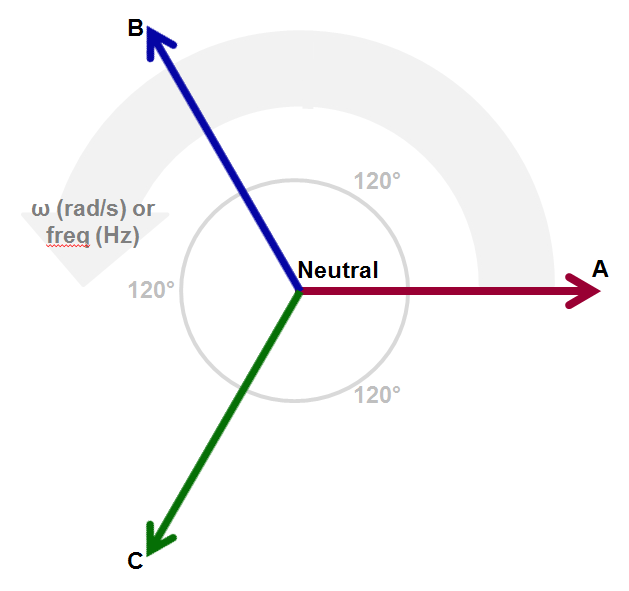
The resulting time-varying, "rotating" voltage vectors appear as three sinusoidal waveforms. They are separated by 120° in phase and are of equal peak amplitude.
The voltage value is calculated as: Vx * sin(α), where Vx is the magnitude of the phase voltage vector and α is the angle of rotation (in radians).
There are a variety of reasons for using three-phase AC voltage:
In three-phase systems, voltage can be thought of, and measured, in two ways (Figure 3). One way is to measure line-to-line, or phase-to-phase. Such measurements may be referenced from VA to VB (or VA-B for simplicity), for example. The second possibility is to measure line-to-neutral; for example, from neutral to VA (or VA-N for simplicity). For such measurements, of course, neutral must be both present and accessible.
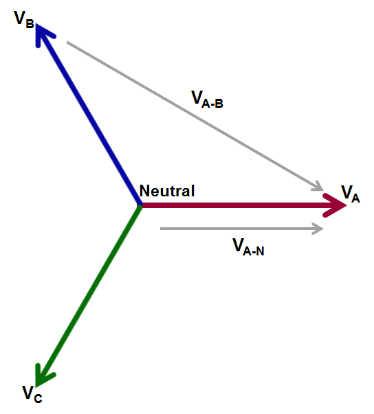
Note that the line-to-line vectors are longer than the line-to-neutral vectors. Thus, magnitudes of line-to-line voltages are typically larger than line-to-neutral voltages. It's more common to probe and acquire line-to-line voltages, because while a neutral point may not always be present, there will always be the three lines. Also, line-to-line measurements may be converted to line-to-neutral values and vice versa. The differences between them boil down to a 30° difference in phase and a magnitude difference of √3.
Copyright © 2020-2026 Teledyne LeCroy. All rights reserved. All original content, including text and photos, is the property of Teledyne LeCroy and cannot be reproduced without expressed written permission.

Electrical power spans generation, distribution, and consumption—where motors and modern power electronics dominate global energy use and measurement challenges.

AC line power is a rotating voltage vector measured in RMS terms, with peak, peak-to-peak, and rectified values that differ significantly from the familiar “120 VAC” rating.

AC line current is a rotating sinusoidal vector—single- or three-phase—whose accurate measurement depends on system configuration and the right choice of current sensor.

Understanding Wye and Delta configurations and line-line versus line-neutral voltages is essential for accurate three-phase AC calculations.