On-Die Power Rail Measurements: Setup and Best Practices
Accurate on-die power rail measurements depend on proper sense-line design, differential probing, and careful test setup at the package level.
Accurate on-die power rail measurements depend on proper sense-line design, differential probing, and careful test setup at the package level.

Transmission line losses—driven by skin effect and dielectric properties—play a critical role in degrading high-speed signal integrity and eye performance.
Transmission line loss directly affects eye diagram quality, with around −12 dB at Nyquist marking the limit before signal integrity rapidly degrades without equalization.
AC line power is a rotating voltage vector measured in RMS terms, with peak, peak-to-peak, and rectified values that differ significantly from the familiar “120 VAC” rating.


Having reviewed a broad definition of power, how it is generated and distributed, and how motors consume almost half of all generated power, we will now turn to a more detailed discussion of just what it is that we call "power." When we discuss "power," we're typically referring to what comes out of a wall socket: AC line, or sinusoidal, power.
We refer to AC sinusoidal line voltage by various names: Grid voltage, household voltage, power line, utility power, mains, and so on. They're all the same thing. Most often, the term we hear is "VAC" or just V. What that really means is an RMS (root mean square) voltage rating. You'll hear these terms used interchangeably in the context of discussions of AC line power.
Single-phase AC systems can comprise either two or three wires. Here in the United States, the typical 115-V system carries two wires, while a 240-V system comprises two hot wires and a neutral line.
Three-phase wiring can be of either three or four wires. Multi-phase systems can be of more than three phases; this isn't something that utilities typically provide but it could be achieved locally with some form of power conversion. Most often, four to six phases come into play for redundancy's sake in military/aerospace applications so that even if a phase (or two) fail, the system will remain operational.
When engineers measure AC sinusoidal voltage, it's important to establish a reference point. In a single- or two-phase system, the measurement is typically taken against a neutral line. However, in a three-wire system, the measurement can be from hot line to hot line, or from phase to phase. If it's a three-phase system, measurements can be from line to neutral or from line to line. Remember that a neutral line isn't the same thing as a ground, which is a safety connection from chassis to earth ground. Also, note that the shape of an AC sinusoidal voltage is nominally a sine wave, but it's never a pure sine wave. In the real world, utility voltages always carry some amount of distortion.
How should we think of AC line voltage? Fundamentally speaking, it's a single voltage vector with a magnitude (expressed in volts) and a phase angle. Thinking of it in this way helps one to understand why the voltage attains its sinusoidal shape over time. Typically, a single-phase voltage is referred to as "line voltage."
That single-phase voltage vector, depicted in Figure 1, rotates at a given frequency, which, for typical utility voltages, is 50 to 60 Hz (sometimes that's expressed in radians/s). At any given moment in time, the voltage magnitude is:
where V = the magnitude of the voltage vector and α = the angle of rotation, in radians. As the vector rotates, the magnitude changes. Thus, at any given moment in time, the magnitude is as shown above. The resulting time-varying "rotating" voltage vector appears as a sinusoidal waveform with a fixed
frequency of 50 Hz in Europe (period of 20 ms), 60 Hz in the United States (period of 16.67 ms), and either 50 or 60 Hz in Asia. You might see other frequencies associated with power from sources other than utilities, such as 400 Hz in U.S. Navy applications or 25 Hz in mining scenarios.
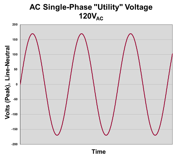
When you hear someone say "120 VAC," that's an RMS value. Referring to Figure 2, note that the waveform exhibits peak and peak-to-peak voltages that are much higher than 120 V. Peak voltage (VPEAK) is:
or, in this case, about 169.7 V. Meanwhile, peak-to-peak voltage (VPEAK-PEAK) may be calculated as:
which, in the present case, is 339.4 V. If this AC voltage were to be rectified and filtered, it would be:
While we're on the subject of RMS values, you'll sometimes see references to "true RMS" voltages. "True RMS" is in fact not an engineering-based definition, but rather something that some marketing departments use to describe a mathematically correct RMS calculation as compared to a measurement shortcut taken by inexpensive instruments.
For example, a budget multimeter might calculate RMS using VPEAK-PEAK / √2. The result of such a calculation should actually be referred to as "false RMS," as it is only a valid calculation for a pure sine wave, which can rarely be assumed to be present.
Any sampling technology, such as you find in digital oscilloscopes or power analyzers, will calculate VRMS or IRMS correctly. However, you won't find the makers of these instruments marketing their VRMS calculation as "true RMS."
Copyright © 2020-2026 Teledyne LeCroy. All rights reserved. All original content, including text and photos, is the property of Teledyne LeCroy and cannot be reproduced without expressed written permission.

Electrical power spans generation, distribution, and consumption—where motors and modern power electronics dominate global energy use and measurement challenges.

Three-phase AC voltages consist of three balanced sinusoidal vectors separated by 120°, with measurable differences between line-to-line and line-to-neutral values.

AC line current is a rotating sinusoidal vector—single- or three-phase—whose accurate measurement depends on system configuration and the right choice of current sensor.

Understanding Wye and Delta configurations and line-line versus line-neutral voltages is essential for accurate three-phase AC calculations.