On-Die Power Rail Measurements: Setup and Best Practices
Accurate on-die power rail measurements depend on proper sense-line design, differential probing, and careful test setup at the package level.
Accurate on-die power rail measurements depend on proper sense-line design, differential probing, and careful test setup at the package level.

Transmission line losses—driven by skin effect and dielectric properties—play a critical role in degrading high-speed signal integrity and eye performance.
Transmission line loss directly affects eye diagram quality, with around −12 dB at Nyquist marking the limit before signal integrity rapidly degrades without equalization.
Understanding Wye and Delta configurations and line-line versus line-neutral voltages is essential for accurate three-phase AC calculations.


Our last post in this series on the essential principles of power covered the basics of three-phase voltages: their composition of three voltage vectors, how they're generated, how they're measured (line-line or line-neutral), and conversion of line-line values to line-neutral values. Here, we'll pick up the thread with more on three-phase AC voltages.
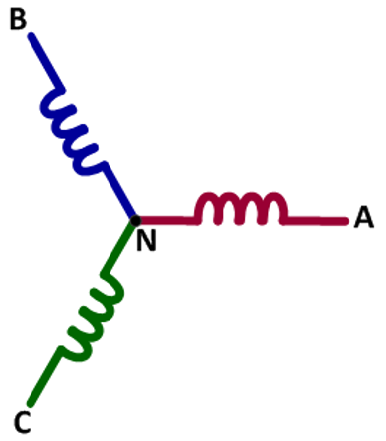
There are different connection configurations for three-phase lines, two of these being the Wye (Y) and Delta (Δ) configurations. The former (Figure 1) is likely the most common configuration. In the Wye connection, you'll see three coils with a terminal and neutral interrupted by a coil as in a transformer. Neutral is always present in the Wye connection but in many cases is not accessible.
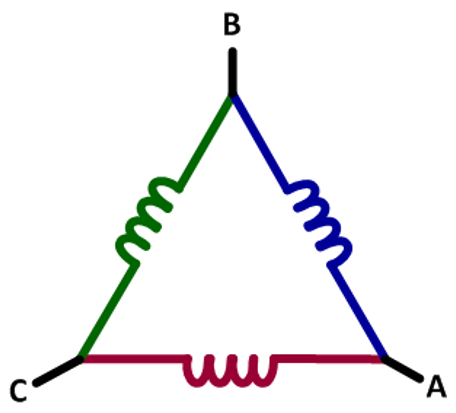
Meanwhile, the Delta connection (Figure 2) typically does not have a neutral terminal. However, some utility equipment manufacturers who build Delta systems will create a neutral winding somewhere to allow a split winding. You'll see this sometimes in motors but not in transformers.
It's important to understand that you'll often see voltage referred to as VAC, but what is actually present is VRMS. AC-voltage ratings are always for line-line voltage values; the typical value in the U.S. is 480 V.
The three phases are usually known as A, B, and C, with the line-line voltages being A-B (VA-B), BC (VB-C), and C-A (VC-A). Sometimes you'll see these voltages referred to as phase-phase voltages.
For three-phase systems, you can calculate the peak and peak-to-peak voltages. For the former,
while for the latter,
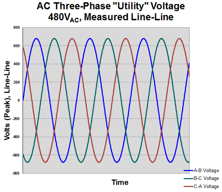
Figure 3 depicts a three-phase "utility" voltage of 480 VAC, with all three phases shown as line-line voltages. In this case, the peak voltage is about 680 V and the peak-to-peak voltage is near twice that at about 1400 V.
If the neutral line is present in a given wiring configuration, then we can measure three-phase voltages as line-neutral voltages. The equations for these calculations are as follows:
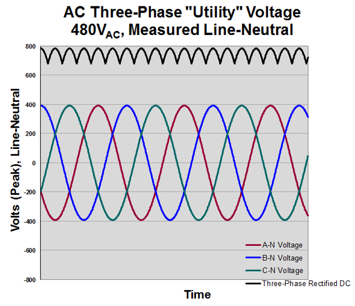
Even though a configuration as such is described as a 480-V AC system, in this case it's actually 277 V (Figure 4). If you should see or hear a reference to a "480 277," it's because the reference is to line-line or line-neutral. The calculations shown above are much like the line-line calculations, so the peak voltage is almost 400 V and peak-to-peak voltage almost 800 V.
If all three phases are rectified, filtered, and summed, you get a DC value of 679 V using:
The practical maximum filtered DC bus voltage is less than the sum of the vectors. Note that Figure 4 depicts the DC added after rectification but does not show it filtered.
An eyeball comparison of Figures 3 and 4 (line-line and line-neutral voltages, respectively) shows the magnitude difference between them. There's also a slight phase difference of about 30°.
You may have heard references to utility AC voltage classes, which are defined for standards organizations such as ANSI in the United States and IEC in Europe. The following definitions are per ANSI C84.1-1989.
First, the low-voltage 50-V class isn't really a "class" as such but rather a safety rating. Fifty volts is considered safe for exposure to uninsulated conductors.
The low-voltage 600-V class is a distribution voltage class that covers:
The definition of medium voltages for power generation, distribution, and sub-transmission comprises "classes" of 5 kV, 15 kV, 25 kV, 35 kV, and 69 kV.
Copyright © 2020-2026 Teledyne LeCroy. All rights reserved. All original content, including text and photos, is the property of Teledyne LeCroy and cannot be reproduced without expressed written permission.

Electrical power spans generation, distribution, and consumption—where motors and modern power electronics dominate global energy use and measurement challenges.

AC line power is a rotating voltage vector measured in RMS terms, with peak, peak-to-peak, and rectified values that differ significantly from the familiar “120 VAC” rating.

Three-phase AC voltages consist of three balanced sinusoidal vectors separated by 120°, with measurable differences between line-to-line and line-to-neutral values.

AC line current is a rotating sinusoidal vector—single- or three-phase—whose accurate measurement depends on system configuration and the right choice of current sensor.