On-Die Power Rail Measurements: Setup and Best Practices
Accurate on-die power rail measurements depend on proper sense-line design, differential probing, and careful test setup at the package level.
Accurate on-die power rail measurements depend on proper sense-line design, differential probing, and careful test setup at the package level.

Transmission line losses—driven by skin effect and dielectric properties—play a critical role in degrading high-speed signal integrity and eye performance.
Transmission line loss directly affects eye diagram quality, with around −12 dB at Nyquist marking the limit before signal integrity rapidly degrades without equalization.
PCIe 6.0 compliance requires SNDR and RLM results with oscilloscope noise removed—these three methods show how to compensate noise accurately in real test setups.

The SDAX-PCIE6 option for use with Teledyne LeCroy Serial Data Expert software and Teledyne LeCroy oscilloscopes enable you to quickly make new PCI Express® 6.0 noise measurements SNDR and RLM with the oscilloscope baseline noise removed, as required by the standard.
Here's a brief description of the three, proprietary noise removal methods from which you can choose.
Manual uses the specified amount of oscilloscope noise for the 𝜎scope variable in the SNDRnr formula (described in the last post). This method is useful if you have previously measured your oscilloscope baseline noise and know what value to enter.
Baseline saves a reference of the input terminated into 50 𝝮, which is then compared to the unterminated input to determine the oscilloscope's intrinsic noise floor. The calculated oscilloscope noise is then computed into the SNDRnr measurement results. To use this method, you will save a Single acquisition of the unequalized Q0 signal, then connect the signal to a pair of 50 𝝮 terminators and measure again.
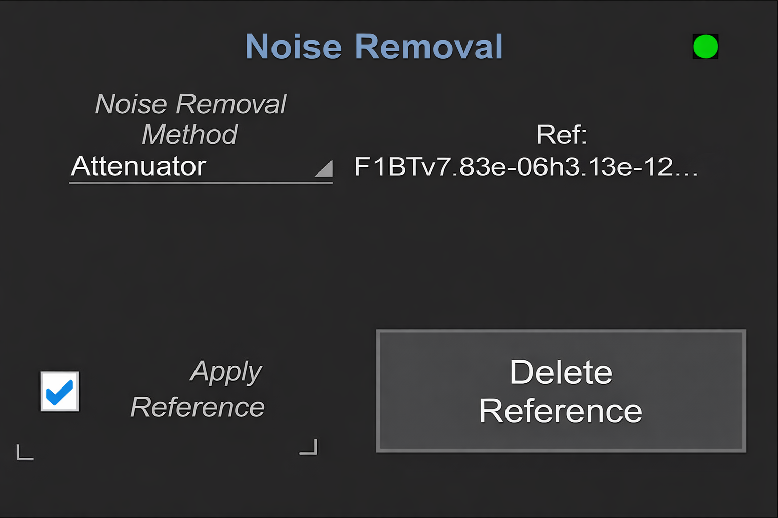
The Attenuator method is the most accurate noise compensation method, since a signal is being applied to the oscilloscope for both reference and measurement. It compares the SNR of a full-scale signal to the SNR of an attenuated signal (at the same full-scale input range) to calculate the oscilloscope's noise contribution to the SNDR as per the formula:
𝜎FS² = 𝜎scope² + 𝜎signal²
𝜎Att² = 𝜎scope² + (𝜎signal² / K²)
𝜎scope² = (K²𝜎Att² – 𝜎FS² / K²– 1)
where K is the attenuation value.
The 𝜎scope value is computed into the SNDRnr measurement results.
To use the Attenuator method, you will take a baseline measurement without attenuation, then connect a pair of 6 dB or 10 dB attenuators between the oscilloscope and DUT and measure again.
For the full step-by-step instructions, download our application note,
Making New PCIe 6.0 Compliance Pattern Measurements with Your Oscilloscope.
Reference waveforms must be saved on the same day you make measurements, using the exact same equipment. When you change any part of your setup, or start a new test session, choose Delete Reference and repeat the procedure to save it before proceeding with measurements.
Copyright © 2020-2026 Teledyne LeCroy. All rights reserved. All original content, including text and photos, is the property of Teledyne LeCroy and cannot be reproduced without expressed written permission.

Understanding PCIe’s layered architecture reveals why capturing synchronized physical- and protocol-layer behavior is essential for effective link debugging.


CrossSync PHY enables time-synchronized protocol and oscilloscope analysis to diagnose unexpected PCIe link equalization and preset training behavior.


CrossSync PHY enables time-synchronized oscilloscope and protocol analysis to verify PCIe L1 substate clock request and reference clock timing.

PCIe 6.0’s move to PAM4 signaling introduces new compliance pattern measurements—SNDR, RLM, and ps21TX—that require updated test methodologies and noise-aware analysis.