On-Die Power Rail Measurements: Setup and Best Practices
Accurate on-die power rail measurements depend on proper sense-line design, differential probing, and careful test setup at the package level.
Accurate on-die power rail measurements depend on proper sense-line design, differential probing, and careful test setup at the package level.

Transmission line losses—driven by skin effect and dielectric properties—play a critical role in degrading high-speed signal integrity and eye performance.
Transmission line loss directly affects eye diagram quality, with around −12 dB at Nyquist marking the limit before signal integrity rapidly degrades without equalization.
CrossSync PHY enables time-synchronized oscilloscope and protocol analysis to verify PCIe L1 substate clock request and reference clock timing.


Debugging the L1 substates used for PCIe® power management has been a real pain point for engineers, especially those using the M.2 form factor. The L1.1 and L1.2 substates allow you to take a PCIe link to a deeper power savings state than L1 alone. L1 is entered by either of two mechanisms, an ASPM message or a Power Management message, but in both cases the net effect is that the link goes into electrical idle. Unlike conventional L1, a clock request (CLKREQ#) signal is used to enter and exit the L1 substates. Upon entry, the device or host deasserts the clock request line. By saying, “I don’t require a clock anymore,” the clock can be turned off for additional power savings. Upon exiting the L1 substates, the CLKREQ# is asserted and the reference clock resumes.
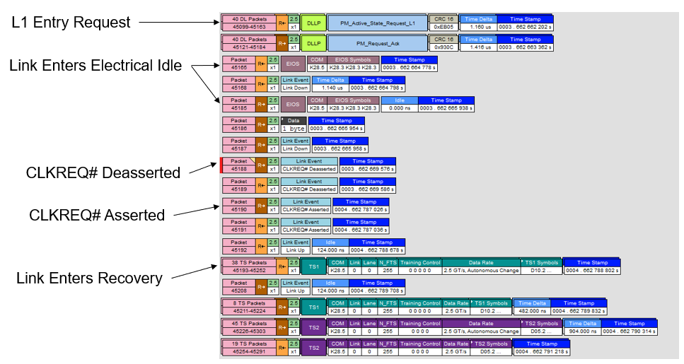
In a protocol analyzer, these substates would not really be visible other than the toggling of the clock request line. You would see a request to enter L1, and after it is acknowledged you’d see the EIOS, which is the last ordered set before the link drops to the electrical idle state, then the clock request line being deasserted. But you would not see what really happens with the clock request line during this time from an electrical point of view—that requires an oscilloscope. If there were problems with the timing from the clock request assertion to the reference clock becoming valid, that would not be visible to you on a protocol analyzer, but this is exactly the kind of problem you can debug using CrossSync™ PHY for PCIe.
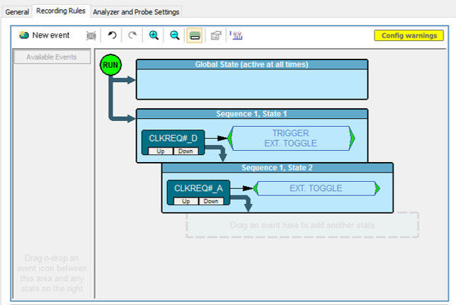
The CrossSync PHY technology uses the protocol analyzer to trigger the oscilloscope on higher-level protocol events, like clock requests. You would set the protocol analyzer to trigger the oscilloscope when it sees the clock request being deasserted at the entry to L1, at which point both the protocol analyzer and the oscilloscope begin acquiring data. Sequence mode can be used to make two oscilloscope acquisitions of the reference clock signal at only the times you care about—one at the entry to L1 and one at the exit—instead of wasting memory on the idle time between.
By navigating the cross-triggered, time synchronized acquisitions side-by-side, you can be assured that what you are looking at on the reference clock signal is actually the L1 substate entry/exit. Clicking either the oscilloscope trace or the protocol analyzer packet display within the CrossSync window shifts both displays to the same point in time. You can also use the Navigation Bar to zoom into different time windows on both acquisitions simultaneously.
All the usual oscilloscope tools such as cursors and parameters are available to you to measure the delta time between reference clock and data link events. After identifying the start of a valid reference clock on the oscilloscope acquisition, place a horizontal cursor there and measure the delta of: CLKREQ# assertion to valid ref clock (TL10_REFCLK_ON); valid ref clock to TS1 packet; valid ref clock to SDS packet (start of L0). Having compared when the ref clock actually goes idle and becomes active again to what was happening in the data link layer at the same time, you can determine if the entry and exit is happening within specification and design limits.
Copyright © 2020-2026 Teledyne LeCroy. All rights reserved. All original content, including text and photos, is the property of Teledyne LeCroy and cannot be reproduced without expressed written permission.

Understanding PCIe’s layered architecture reveals why capturing synchronized physical- and protocol-layer behavior is essential for effective link debugging.

CrossSync PHY enables time-synchronized protocol and oscilloscope analysis to diagnose unexpected PCIe link equalization and preset training behavior.

PCIe 6.0’s move to PAM4 signaling introduces new compliance pattern measurements—SNDR, RLM, and ps21TX—that require updated test methodologies and noise-aware analysis.

PCIe 6.0 compliance requires SNDR and RLM results with oscilloscope noise removed—these three methods show how to compensate noise accurately in real test setups.