On-Die Power Rail Measurements: Setup and Best Practices
Accurate on-die power rail measurements depend on proper sense-line design, differential probing, and careful test setup at the package level.
Accurate on-die power rail measurements depend on proper sense-line design, differential probing, and careful test setup at the package level.

Transmission line losses—driven by skin effect and dielectric properties—play a critical role in degrading high-speed signal integrity and eye performance.
Transmission line loss directly affects eye diagram quality, with around −12 dB at Nyquist marking the limit before signal integrity rapidly degrades without equalization.
Understanding phase angle and power factor is essential for correctly calculating real, apparent, and reactive power in sinusoidal AC systems.


Wouldn't it be wonderful if every sine wave we encountered in the real world was pure, with no distortion? It sure would make life easier. Alas, it's pretty much never the case. But in reviewing sinusoidal power calculations, it's best that we begin with the simplest case: a single, pure sinusoidal line voltage and single, pure sinusoidal line current supplying a linear load.
Electric power is the rate at which energy is transferred to a circuit, calculated in units of Watts, with a Watt being an energy-transfer rate of 1 Joule/s. For a purely resistive load fed by a single current vector and single voltage vector,
P = I2R = V2/R = instantaneous V*I
with both vectors perfectly in phase (Figure 1).
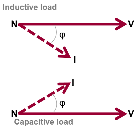
However, a purely resistive load is about as rare in the wild as the pure sine wave. There's typically some amount of inductance or capacitance. Depending on which of those is the dominant characteristic, the current vector will either lead or lag the voltage vector, and the quantity of lag or lead is defined by the phase angle (φ). Phase angle indicates the angular difference between the voltage and current vectors. It can be expressed in degrees (from -90° to +90°), or in radians (from -π/2 to +π/2).
The cosine of the phase angle is known as the "power factor" (PF or λ). Remember that PF = Cos(φ) only for purely sinusoidal waveforms. Power factor is always present in AC systems. It's a unit-less quantity ranging from 0 to 1. For a purely resistive load with V and I in phase, PF = 1. For a purely capacitive or a purely inductive load with V and I 90° out of phase, PF = 0. Power factor is typically not signed: current either leads (capacitive load) or lags (inductive load) voltage (Figure 2).
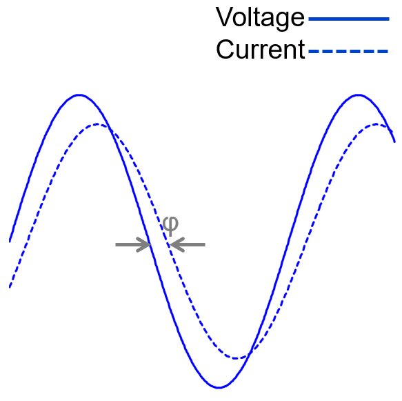
Here's another way in which to think about phase angle. Figure 3 depicts a pure sinusoidal voltage and a pure sinusoidal current. Phase angle can be directly measured between these waveforms. We can see that the current has a different magnitude than the voltage.
At the zero crossing, we can also see that there's a time delay between the waveforms that can be expressed in degrees relative to a full period of 360°. That's the phase angle, and again, if these current and voltage waveforms were feeding a purely resistive load, they would be perfectly in phase and would be directly on top of each other. In this case, current leads voltage, indicating a capacitive load. Thus, for a single-phase, non-resistive load (meaning that it's either capacitive or inductive), P ≠ V*I, and we must account for the phase angle.
To break things down further, there are three different types of power:
Q = √(S2-P2)
Reactive power is not consumed, which is to say it's not transferred to the load during a power cycle, but rather simply circulates in the circuit during operation.
So to conclude, AC line voltages are very different from the 5- or 3.3-V logic voltages familiar to many engineers. Three-phase systems are a complex mix of magnitude, phase, and rotation, and they introduce different measurement challenges, such as the lag/lead of current vectors relative to voltage vectors. That results in more than one type of power (real, apparent, and reactive), so line "power" isn't a simple P = V*I situation.
Copyright © 2020-2026 Teledyne LeCroy. All rights reserved. All original content, including text and photos, is the property of Teledyne LeCroy and cannot be reproduced without expressed written permission.

Electrical power spans generation, distribution, and consumption—where motors and modern power electronics dominate global energy use and measurement challenges.

AC line power is a rotating voltage vector measured in RMS terms, with peak, peak-to-peak, and rectified values that differ significantly from the familiar “120 VAC” rating.

Three-phase AC voltages consist of three balanced sinusoidal vectors separated by 120°, with measurable differences between line-to-line and line-to-neutral values.

AC line current is a rotating sinusoidal vector—single- or three-phase—whose accurate measurement depends on system configuration and the right choice of current sensor.