On-Die Power Rail Measurements: Setup and Best Practices
Accurate on-die power rail measurements depend on proper sense-line design, differential probing, and careful test setup at the package level.
Accurate on-die power rail measurements depend on proper sense-line design, differential probing, and careful test setup at the package level.

Transmission line losses—driven by skin effect and dielectric properties—play a critical role in degrading high-speed signal integrity and eye performance.
Transmission line loss directly affects eye diagram quality, with around −12 dB at Nyquist marking the limit before signal integrity rapidly degrades without equalization.
Accurate EMC/ESD testing begins with verifying surge and ESD pulse characteristics—such as rise time and bandwidth—using high-speed oscilloscopes before applying them to the DUT.


There are many circumstances in which electromagnetic compatibility (EMC) and electrostatic discharge (ESD) testing are a fact of life. Many countries have adopted IEC international standards that dictate certain levels of immunity, as have the automotive, medical, military, and aerospace industries. In this post, we'll begin looking at how oscilloscopes figure into tests for both radiated and conducted EMC/ESD immunity.
First, let's consider just what kind of EMC/ESD testing oscilloscopes are used for. The overall scope of EMC/ESD testing falls into four broad quadrants (Figure 1). Of those four, oscilloscopes come into play in the two shaded in green: radiated and conducted immunity. In the former case, we want to know if the equipment under test (EUT) can withstand EMC/ESD emissions in free space or via cables. In the latter, we're investigating whether the EUT is susceptible to transient pulses arising from switching or to surges.

The typical test setup for conducted immunity calls for generating a burst, surge, or ESD pulse. You want to verify the shape of the pulse from the pulse generator using an oscilloscope, with which you'll examine parameters such as rise/fall times, pulse width, frequency, and pulse or burst repetition interval. After "testing the tester," the ESD source will be applied to the actual DUT. But oscilloscopes come into play in the preliminary stage to test the ESD gun and surge tester.
Most ESD testing follows the IEC 61000-4 standard that must be met for products to earn the CE mark. Figure 2 shows a diagram from the specification showing the current shunt target and where the ESD gun should connect to it. At right in Figure 2 is a depiction of an idealized IEC 61000-4-2 pulse. Such a pulse has a very fast rise time followed by an exponential decay that may hit several bumps as it deteriorates.
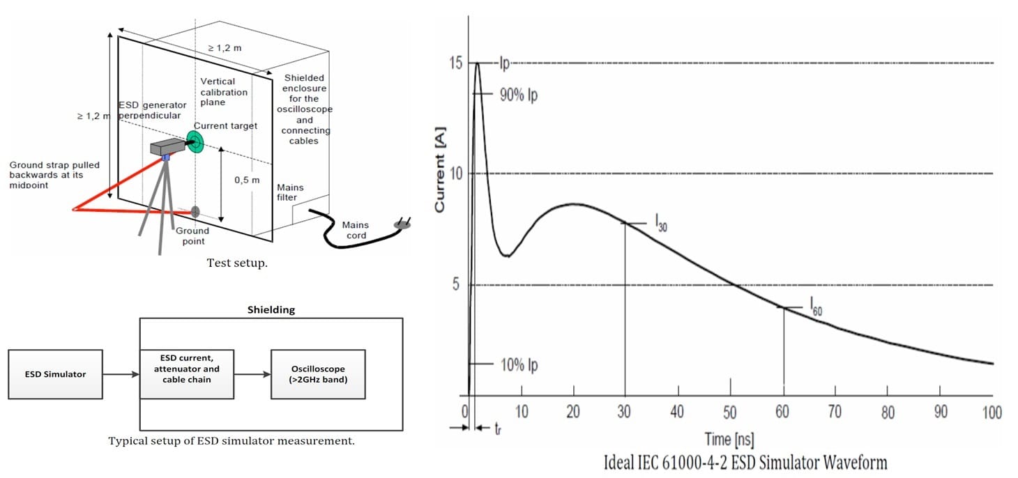
Typically, rise and fall times for ESD pulses fall in the range of 0.7 to 1.0 ns. Measurement calls for the capture of a single pulse and to measure and verify its rise time (for positive-going pulses) or fall time (for negative-going pulses). For the most part, required oscilloscope bandwidths are 1, 2, or 4 GHz. However, some of the newer ESD standards are drawing bandwidths up into the 16 to 20 GHz range to accommodate very fast pulse rise times.
Copyright © 2020-2026 Teledyne LeCroy. All rights reserved. All original content, including text and photos, is the property of Teledyne LeCroy and cannot be reproduced without expressed written permission.

Accurate ESD pulse measurement depends on using a high enough sampling rate to capture sufficient points on the rising edge for reliable characterization.

Standard IEEE pulse definitions can misinterpret fast-decaying ESD pulses, requiring manual threshold adjustments for accurate measurements.

A real-time oscilloscope can help engineers identify EMI sources and reduce radiated emissions before submitting products for costly FCC compliance testing.