On-Die Power Rail Measurements: Setup and Best Practices
Accurate on-die power rail measurements depend on proper sense-line design, differential probing, and careful test setup at the package level.
Accurate on-die power rail measurements depend on proper sense-line design, differential probing, and careful test setup at the package level.

Transmission line losses—driven by skin effect and dielectric properties—play a critical role in degrading high-speed signal integrity and eye performance.
Transmission line loss directly affects eye diagram quality, with around −12 dB at Nyquist marking the limit before signal integrity rapidly degrades without equalization.
Continuous Time Linear Equalization (CTLE) enhances high-speed serial signals by compensating for channel loss, improving eye openings while balancing noise performance.

We've been looking at the broad topic of debugging high-speed serial links, and in that context, we're also touching on ways to improve signal performance on the receiver side. One of those ways is to implement continuous time linear equalization (CTLE).
We know that a serial-data channel will attenuate the signal, and that it will attenuate higher frequencies more than lower frequencies. CTLE endeavors to boost the higher frequencies at the receiver to bring all frequency components of the signal to a similar amplitude, which in turn boosts jitter and eye-diagram performance. We're looking to equalize the combined characteristics of the transmitter and channel, thereby removing inter-symbol interference (ISI) at the received signal sampling points.
A CTLE implementation is operating on an analog input signal after it's been sampled by a sample- and-hold circuit. We call it "linear" because there are no non-linear components. It's typically modeled as a two-pole (one zero) finite impulse response (FIR) filter.
Different DC gain values are chosen for the filter poles depending on the channel loss characteristics. If it happens to be a low-loss channel of short physical length, that gain value will approach 0 dB, meaning that there's not a lot of equalization happening. But because we're trying to create an inverse of the channel, there still needs to be some CTLE. Having said that, we don't want to over-equalize by boosting high frequencies more than necessary, because that will degrade noise performance.
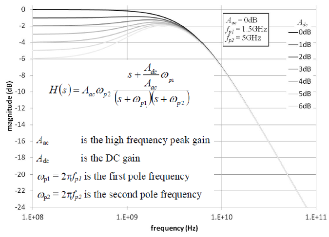
The zero and first pole in the equalizer should ideally be placed as close as possible for good CTLE performance. The first zero provides the high-frequency boost that opens the eye diagram. The first pole avoids peaking at the center of the eye, while the second pole limits the bandwidth. You want to avoid equalizing the entire band with the noise frequencies. Over-equalizing will also risk creating a non-linear phase response. Figure 1 shows the amplitude response only. Given that the equalizer is a linear continuous time system, we'd expect phase response to be linear. If it's not, chances are that too much CTLE is being applied.
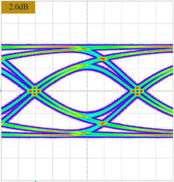
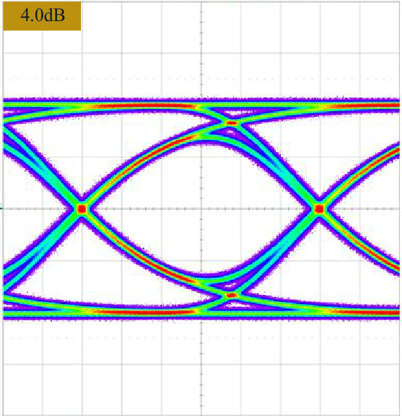
A couple of screen grabs with varying amounts of CTLE applied to a data stream can illustrate the effects. Without any CTLE, the signal's noise performance is decent but the eye itself is sub optimal. Figure 2 shows the effects of 2 dB of CTLE. As you go higher in boost, the eye opens further and further, as can be seen in Figure 3 where 4 dB of CTLE is in effect.
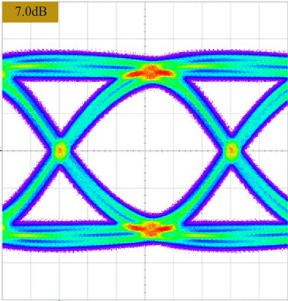
However, with more boosting of the higher frequencies comes degradation of noise performance. The purple fuzz surrounding the eye diagram becomes more and more prominent, as can clearly be seen in Figure 4 with 7 dB of CTLE. In most cases, receive-side CTLE implementations are adaptive, with link-training sequences exchanged between transmitter and receiver to arrive at an optimal CTLE setting.
Copyright © 2020-2026 Teledyne LeCroy. All rights reserved. All original content, including text and photos, is the property of Teledyne LeCroy and cannot be reproduced without expressed written permission.

Channel equalization uses transmitter and receiver techniques to counteract losses, reduce ISI, and improve signal quality in high-speed data links.

Transmit de-emphasis enhances eye diagrams by reducing inter-symbol interference, improving signal clarity at the cost of lower overall amplitude.

S-parameters allow engineers to model, remove, or simulate channel effects in high-speed serial links, helping diagnose signal degradation and improve performance.

TDME oscilloscope software enables engineers to measure serial bus performance and convert encoded data into analog waveforms for deeper debugging and analysis.
