On-Die Power Rail Measurements: Setup and Best Practices
Accurate on-die power rail measurements depend on proper sense-line design, differential probing, and careful test setup at the package level.
Accurate on-die power rail measurements depend on proper sense-line design, differential probing, and careful test setup at the package level.

Transmission line losses—driven by skin effect and dielectric properties—play a critical role in degrading high-speed signal integrity and eye performance.
Transmission line loss directly affects eye diagram quality, with around −12 dB at Nyquist marking the limit before signal integrity rapidly degrades without equalization.
What if we remove the probes from the equation by connecting our DUT's output directly to the oscilloscope's analog input using a 3-ft. 50-Ω coaxial cable?

In our recent exploration of 10x passive probes, we've determined that while these types of probes are great general-purpose tools, they're not necessarily going to do the job in specialized measurement circumstances. They're relatively low-bandwidth, low-SNR probes that impose some limitations and, in some scenarios, can deliver potentially misleading or erroneous measurement results if used without clear understanding of their capabilities.
But what if we remove the probes from the equation by connecting our DUT's output directly to the oscilloscope's analog input using a 3-ft. 50-Ω coaxial cable? What if we also use a 1-MΩ input impedance on our oscilloscope when doing so?
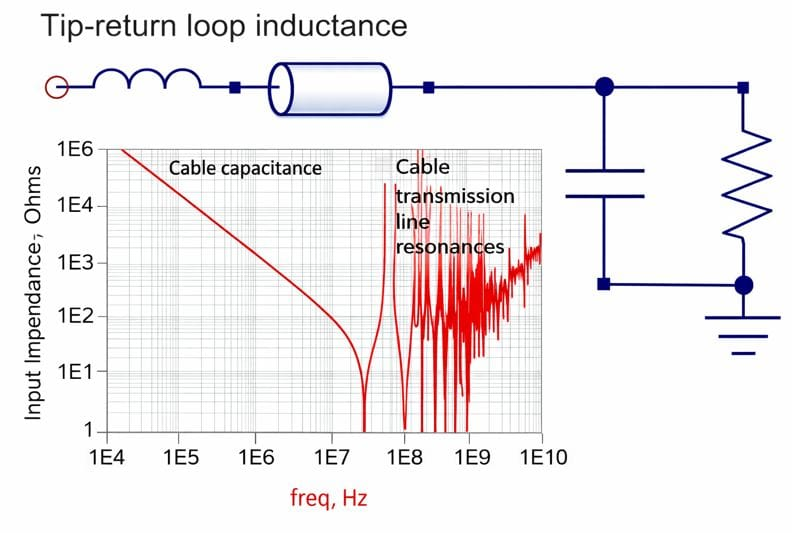
As Figure 1 reveals, a 50-Ω coaxial cable exhibits high impedance at low frequencies, but there's the input impedance imposed by the cable's capacitance to consider. At low frequency, the cable looks like a capacitor of roughly 100 pF (30 pF/foot for RG-58 coax). That's about 10x the capacitive load of the 10x passive probe.
If you're using the oscilloscope's 1-MΩ input, at low frequencies this will look like a 100-pF load. As frequency increases to, say, the 10-MHz range, we'll see some low impedances in the range of 10-100 Ω. That can load down your DUT considerably. It's like adding a 100-pF capacitor to your circuit.
At higher frequencies, the coax will look more like a transmission line, and the signal will bounce back and forth with reflections. With the oscilloscope input set for 1-MΩ impedance and depending on the impedance of the DUT, ringing is a possibility.
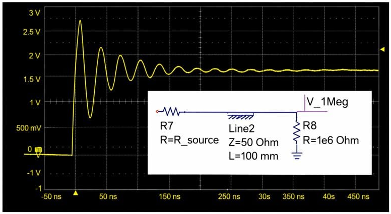
This is a scenario where situational awareness is critical. We have to know the source impedance of the DUT to understand the impact of reflections. If the source impedance driving the cable is 50 Ω, there's no problem. We'll get half the voltage into the transmission line, it travels down the line, sees the high impedance at the oscilloscope input, bounces back, and is terminated by the source impedance.
But rarely will our DUT present a 50-Ω source impedance to the transmission line. If it's a very low-impedance source, such as a power rail, we'll see a lot of reflection between the source and the 1-MΩ impedance of the oscilloscope input (Figure 2).
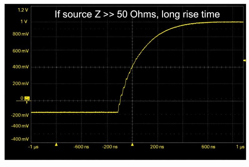
If it's a high-impedance source, we won't get much voltage launched into the line. The signal will reflect back and forth and gradually build up with a long rise time, looking like an RC filter charging up (Figure 3), even though it isn't one.
If we're working with frequencies in the range of 20-50 MHz and signals at volt levels, we're just as well served, if not better, by simply using our 10x passive probe, which won't load down the DUT nearly as much as the coaxial cable will. At, say, 10-20 MHz, the cable is usable as long as we bear in mind that it presents a 100-pF load as noted above.
If we want high bandwidth and we want to use a 50-Ω cable, then we need to terminate the cable with a 50-Ω impedance at the oscilloscope input. We can achieve very high bandwidths this way. However, we cannot use AC coupling in the oscilloscope. For high DC impedance, we'll need to use an external coaxial DC-blocking capacitor. But, if we use that blocking capacitor and we're using the 50-Ω input to eliminate reflections, we've made a high-pass filter and we will not be able to see the low-frequency components of the signal.
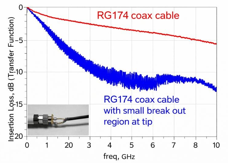
Our bandwidth is still limited by the tip inductance and cable attenuation. One cannot overemphasize how important the tip inductance is. For example, in Figure 4, we see the attenuation of RG-174 coaxial cable alone with good coaxial connections (in red), and we also see the response that we get if we add a small breakout region at the tip (in blue), as if we'd added a coax connector soldered to the board. By simply pulling the signal and return apart and adding perhaps 9 or 10 nH or loop inductance, we reap a dramatic drop in the transfer function.
At the end of the day, if we want to connect our DUT to an oscilloscope using only coaxial cable and coaxial connections and also maximize bandwidth, we want the cleanest interface possible with the least amount of impedance discontinuity.
Copyright © 2020-2026 Teledyne LeCroy. All rights reserved. All original content, including text and photos, is the property of Teledyne LeCroy and cannot be reproduced without expressed written permission.

Accurate on-die power rail measurements depend on proper sense-line design, differential probing, and careful test setup at the package level.

Transmission line losses—driven by skin effect and dielectric properties—play a critical role in degrading high-speed signal integrity and eye performance.

Transmission line loss directly affects eye diagram quality, with around −12 dB at Nyquist marking the limit before signal integrity rapidly degrades without equalization.

This article explains how PDN design, probing method, and measurement location influence power rail noise—and why board-level measurements can be misleading.