On-Die Power Rail Measurements: Setup and Best Practices
Accurate on-die power rail measurements depend on proper sense-line design, differential probing, and careful test setup at the package level.
Accurate on-die power rail measurements depend on proper sense-line design, differential probing, and careful test setup at the package level.

Transmission line losses—driven by skin effect and dielectric properties—play a critical role in degrading high-speed signal integrity and eye performance.
Transmission line loss directly affects eye diagram quality, with around −12 dB at Nyquist marking the limit before signal integrity rapidly degrades without equalization.
Self-aggression noise arises from a device’s own switching activity, creating ripple and rail disturbances even in otherwise steady-state conditions.


Self-aggression noise is so-called because it is inflicted by a component onto itself through its normal operation; nothing else in the system is affecting it. When we look for this, we want to ensure the system is in a steady state, in a place where the noise environment is fairly clear (e.g., the device is on an evaluation board).
An example of self-aggression would be VRM-switching noise. Figure 1 shows ripple on a 900 millivolt rail (yellow trace) at a time when no load is present. One of the things that tells us this is switching noise is that it is synchronous to the PWM clock (red trace). Ripple that is synchronous with the switching clock is a typical figure of merit for identifying switching noise.
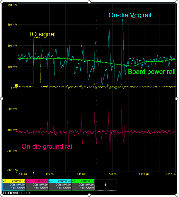
Another example of self-aggression noise occurs on the on-die Vcc rail, shown in Figure 2. As general-purpose IOs switch (one IO being probed is shown by the yellow trace), the IO driver that connects it to the Vcc causes noise spikes on the Vcc rail (the blue trace). This bleeds through to the board power rail (the green trace), as well, causing the dip you see around the time the Vcc spikes are highest. This is a case where on-die noise affects the board, despite the low impedance of the board itself.
It can be challenging to probe the Vcc in order to measure noise. One way you can observe Vcc self-aggression noise is to leave one IO switched to a permanent high state, which is essentially connected through to the Vcc rail. That allows you to observe what's happening on that rail as you induce other effects in the system, such as switching multiple IOs.
The same type of self-aggression occurs within the on-die Vdd, the core logic power rail within the device, although that is much more difficult to observe and usually requires a specially instrumented die.
Copyright © 2020-2026 Teledyne LeCroy. All rights reserved. All original content, including text and photos, is the property of Teledyne LeCroy and cannot be reproduced without expressed written permission.

Accurate on-die power rail measurements depend on proper sense-line design, differential probing, and careful test setup at the package level.

Transmission line losses—driven by skin effect and dielectric properties—play a critical role in degrading high-speed signal integrity and eye performance.

Transmission line loss directly affects eye diagram quality, with around −12 dB at Nyquist marking the limit before signal integrity rapidly degrades without equalization.

This article explains how PDN design, probing method, and measurement location influence power rail noise—and why board-level measurements can be misleading.