On-Die Power Rail Measurements: Setup and Best Practices
Accurate on-die power rail measurements depend on proper sense-line design, differential probing, and careful test setup at the package level.
Accurate on-die power rail measurements depend on proper sense-line design, differential probing, and careful test setup at the package level.

Transmission line losses—driven by skin effect and dielectric properties—play a critical role in degrading high-speed signal integrity and eye performance.
Transmission line loss directly affects eye diagram quality, with around −12 dB at Nyquist marking the limit before signal integrity rapidly degrades without equalization.
Accurate power-rail noise measurement requires handling tiny signals on large DC offsets, best achieved with active probes and proper impedance management.

We've been working through the various challenges in making power-rail noise measurements. One of those challenges is RF pickup that can often swamp the noise signal, and the way around that is to ensure a coaxial connection from the oscilloscope's input down to the power rail itself. We want a high signal-to-noise ratio (SNR), so we're better off with a 1X probe than with a 10X attenuating probe. We want high bandwidth, so we want a 50-Ω termination at the oscilloscope input.
We also need a high DC impedance so we can reduce the current loading on the rail, and we also want to see a very low-level signal in the presence of a large DC offset. How can we accomplish this?
Remember that the 50-Ω terminating resistor inside the analog inputs of most oscilloscopes have a maximum power-dissipation rating of about 0.5 W, which will limit the power-rail voltage we can probe to 5 V or less. We cannot stress this point enough: Do not directly connect a >5-V power rail to the 50-Ω input of your oscilloscope. This will let the magic smoke out of that terminating resistor. If you're unsure of the voltage on a power rail, double-check that your input is set to the 1-MΩ DC-coupled scale!
You might think, well, what if we use AC coupling? You could do that, but most oscilloscopes require a 1-MΩ input resistance with AC coupling. That will reduce the bandwidth of your measurement, invoking that fundamental tradeoff between bandwidth and input impedance.
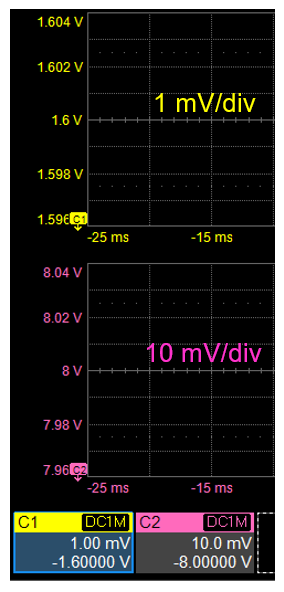
Even if we know for sure that we're probing a low-voltage rail and can afford the imposition of a 50-Ω load, there's the DC-offset problem to contend with. For Teledyne LeCroy's oscilloscopes, the most we can offset on the most sensitive vertical scale of 1 mV/div is 1.6 V (Figure 1). That's OK if we're probing a battery voltage or a 1.2-V rail. If we step up to the 10-mV/div scale, we can offset 8 V. But what if you have a 5- or 10-V rail?
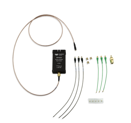
The answer lies in using an active voltage-rail probe (such as Teledyne LeCroy's RP4030). Active voltage-rail probes are built for probing small signals at high bandwidths and with large DC offsets. At DC, the probe looks like a 50-kΩ load, so it draws very little current. But at high frequencies, it looks like a 50-Ω load, so there are no cable reflections. The RP4030 can offset as much as ±30 V, and it does so with 16-bit resolution and 0.5% accuracy. The probe's RMS noise is rated at 140 μV, so it's basically at the noise floor of Teledyne LeCroy's HDO8108A oscilloscope, and provides a 4-GHz bandwidth so you can see harmonics out a good long way.
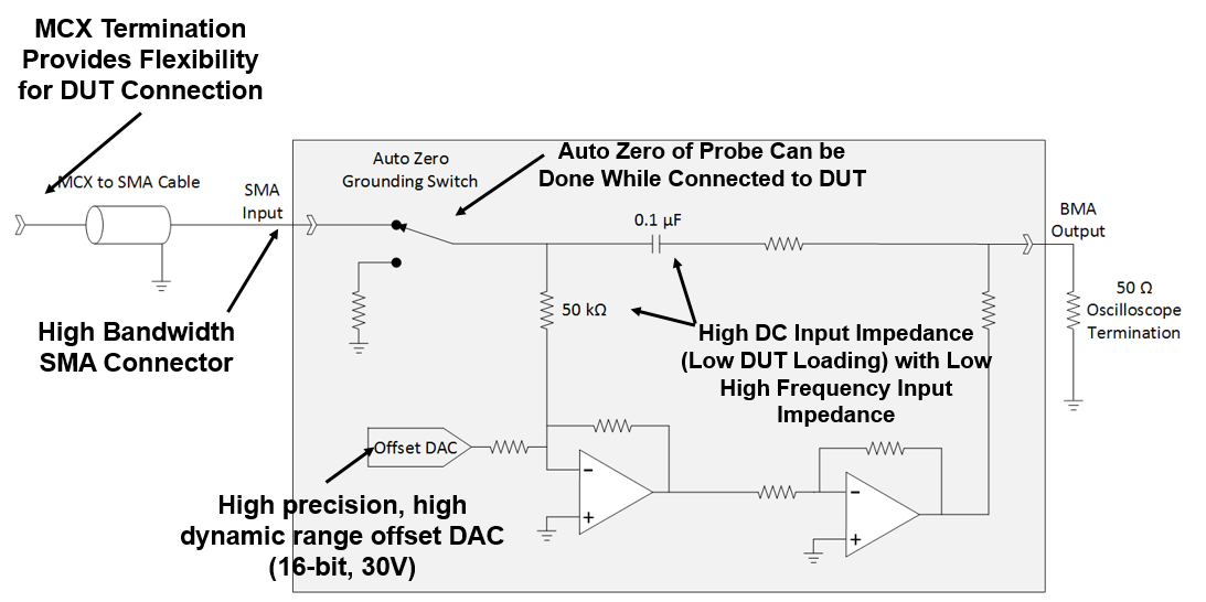
Let's look at an equivalent-circuit diagram of the RP4030 (Figure 3, probe shaded gray) to see how it gets around these various power-rail probing issues. At left is the coax input. Low-frequency DC is blocked by the 0.1-μF capacitance. The signal enters an inverting amplifier where we apply the DC offset with the 16-bit DAC, zeroing out the DC value of the voltage rail. The low-frequency components are passed to another amplifier that can drive the 50-Ω oscilloscope input. High-frequency components pass through the 0.1-μF capacitance directly to the 50-Ω oscilloscope input.
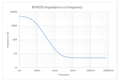
Thus, Figure 4 illustrates how the probe's input frequency looks from a low-impedance source. At low frequencies in the audio range, the impedance remains high so as not to impose a DC load on the DUT. Meanwhile, at high frequencies, the impedance drops down to the 50-Ω region to avoid signal reflections in the cable.
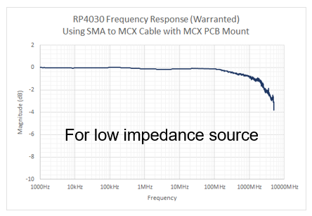
At the same time, the amplifiers and signal path within the RP4030 probe are designed for very high bandwidths. As shown by a plot of the device's transfer function (Figure 5), frequency response is down only 2 dB at 4 GHz for a low-impedance source.
All of the above adds up to a solid combination for voltage-rail noise measurements. In upcoming posts, we will deploy that combination of the HDO8108A oscilloscope and RP4030 active voltage-rail probe to explore the topic of on-die voltage-noise measurements.
Copyright © 2020-2026 Teledyne LeCroy. All rights reserved. All original content, including text and photos, is the property of Teledyne LeCroy and cannot be reproduced without expressed written permission.

Accurate on-die power rail measurements depend on proper sense-line design, differential probing, and careful test setup at the package level.

Transmission line losses—driven by skin effect and dielectric properties—play a critical role in degrading high-speed signal integrity and eye performance.

Transmission line loss directly affects eye diagram quality, with around −12 dB at Nyquist marking the limit before signal integrity rapidly degrades without equalization.

This article explains how PDN design, probing method, and measurement location influence power rail noise—and why board-level measurements can be misleading.