On-Die Power Rail Measurements: Setup and Best Practices
Accurate on-die power rail measurements depend on proper sense-line design, differential probing, and careful test setup at the package level.
Accurate on-die power rail measurements depend on proper sense-line design, differential probing, and careful test setup at the package level.

Transmission line losses—driven by skin effect and dielectric properties—play a critical role in degrading high-speed signal integrity and eye performance.
Transmission line loss directly affects eye diagram quality, with around −12 dB at Nyquist marking the limit before signal integrity rapidly degrades without equalization.
The TF-USB-C-HS enables synchronized electrical probing and protocol analysis to isolate USB 3.2 link training failures at both the PHY and logic layers.


In a USB-C connector, link training for USB 3.1/3.2 is negotiated using an LTSSM (Link Training and Status State Machine) through electrical signaling on the TX1/RX1 and TX2/RX2 connector pins. Link training must be completed on the link before high-speed data transactions can occur. One problem you might encounter during link training is a failure to train to USB 3.2 Gen 2 specifications. Teledyne LeCroy customers report that most system-interoperability problems are caused by either link-training or sideband-negotiation failures, which in turn can result from an electrical problem, a digital problem or a combination of both.
Therefore, more rigorous USB-C link testing is required. The TF-USB-C-HS test coupon fixture enables you to probe all points on the USB-C connector to measure and analyze live links. The insertion-loss profile of the included cable and coupon is tuned to be the equivalent of a golden 0.8-m USB Type-C cable, so you can replace a 0.8-m cable with the coupon and not experience any difference in link performance. The coupon also has a loop to allow a current probe to make load-current measurements, and the HS version is compatible with Teledyne LeCroy DH Series probes for making high-speed differential measurements.
We'll show how to trigger, acquire and decode to find problematic link training packets synchronous with the physical-layer electrical waveforms, so you can tell if the source of your interoperability problem is electrical, logical or both.
Required are:
Recommended are:
The TF-USB-C-HS is connected between the DUT and the Exerciser/Analyzer ports of a Voyager Analyzer (M310e/M310P or M4x), using the included USB-C cable (Figure 2).
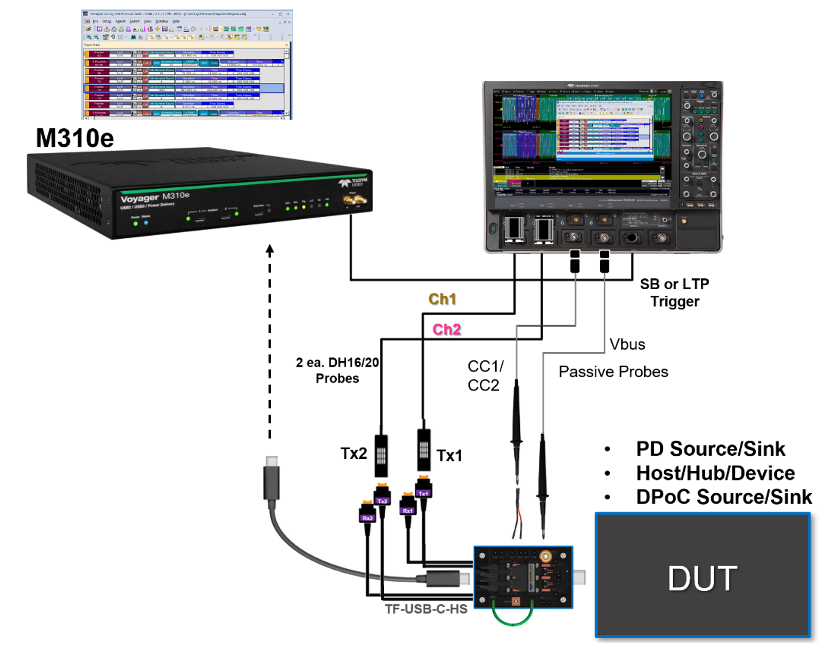
Signals are input to the oscilloscope by way of the test coupon:
Link training issues usually first show up while doing Link Layer or USB Type-C-specific tests using a Voyager protocol analyzer. The protocol analyzer has a rich set of Link Training Packets (LTP) and higher layer analysis of the USB 3.2 LTSSM (Figure 3). In order to trigger an oscilloscope on the area of interest, is necessary to first identify where in the protocol trace the problem is occurring, then set up the protocol analyzer to send a trigger pulse to the oscilloscope at that time.
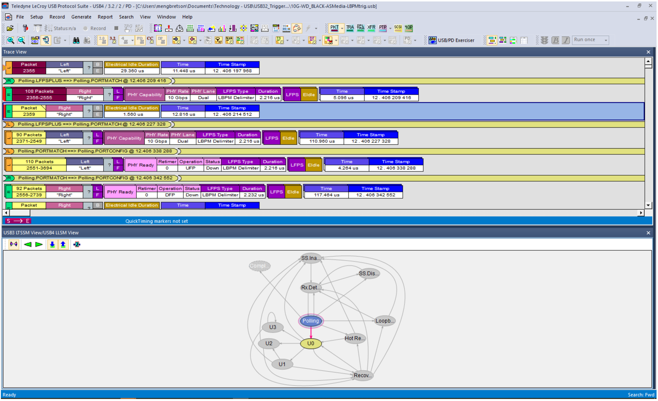
For instance, during Link training, you can send a trigger pulse on SCD1, SCD2, LBPM or an LMP (Link Management Packet). As each trigger event occurs in the signal, the event is marked on the protocol trace and a pulse is sent from the Trigger Out connector of the protocol analyzer to the Ext In trigger input of the oscilloscope, enabling it to capture the electrical signals at virtually the same time.
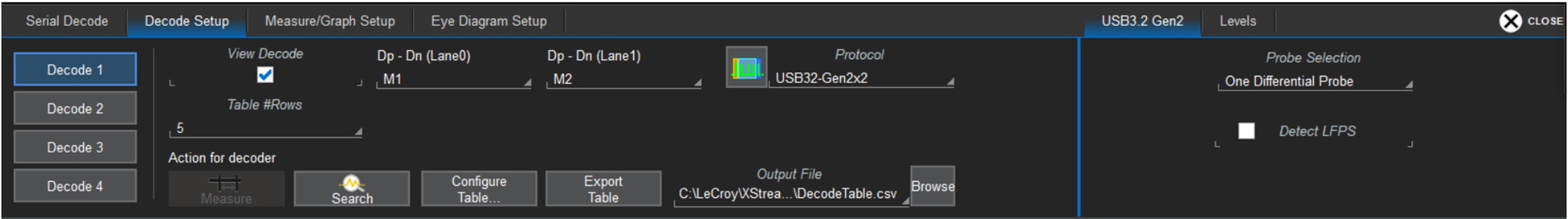
Set up the oscilloscope for an Edge trigger using the Ext In Source.
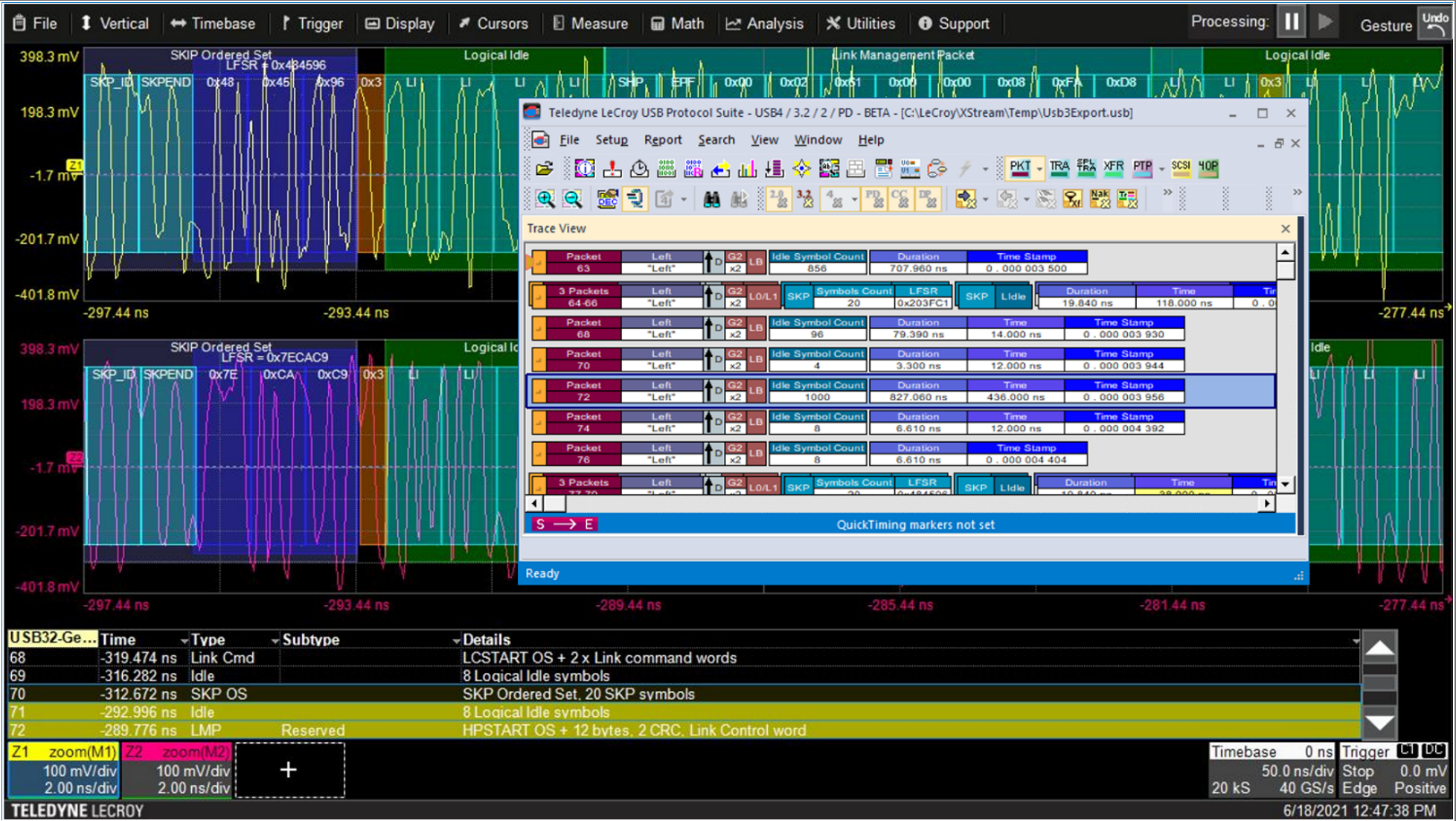
Set up the USB 3.2 D software for Gen2x2 decoding, with One Differential Probe selection. (Note that our example uses acquisitions of Lane0 and Lane1 saved to memories M1 and M2. When probed live, these signals would be on C1 and C2.)
After acquiring, use the decoder Search or Filter feature to find the packet type of interest, which appears in the Type column of the decoder result table. Clicking that row of the table will zoom to the same time in the electrical trace. If you also have the ProtoSync display open (as in Figure 1), you'll also see exactly which protocol packet is involved. If you are using CrossSync PHY, all electrical traces on the oscilloscope and protocol packets are time-synchronized.
A possible source of link training errors is poor signal quality coming from the transmitter. The TF-USB-C-HS provides a convenient way to perform serial data analysis measurements on the transmitters while in a live link. This is not a substitute for physical layer compliance testing, but it can be used to verify that the expected signal quality is coming from the two USB 3.2 transmitters, TX1 and TX2.
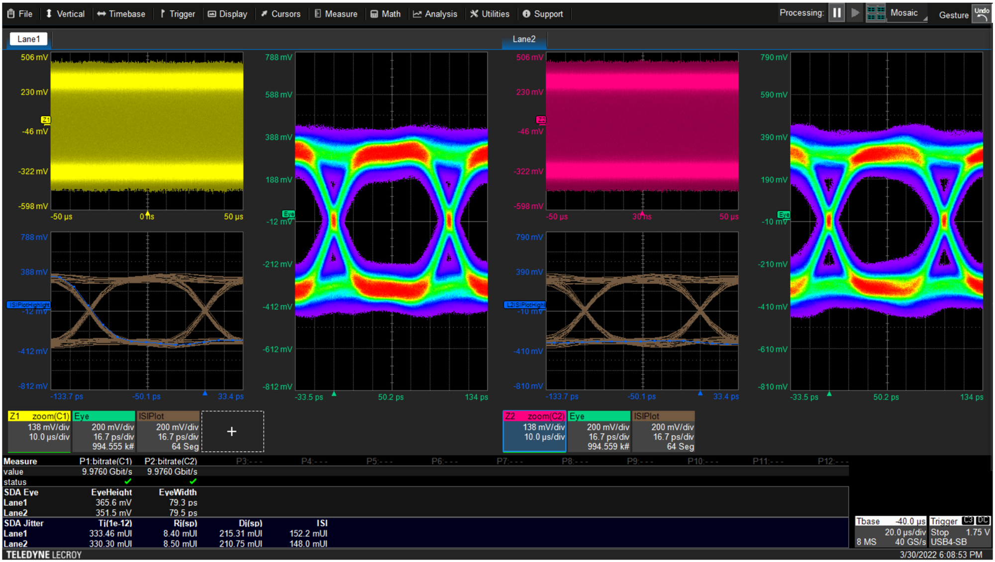
If you have installed the SDAX-COMPLETE serial data oscilloscope software option, a complete set of signal integrity tools is available, including jitter and eye diagram measurements and plots. You can use the eye diagrams to look at the electrical performance of the live link. If the signal is not optimized for the cable it is driving, you may see an eye diagram that has too much or too little equalization. The ISI Plot allows you to evaluate the effect of different pre-emphasis presets on the transmitted eye.
Multi-lane testing with SDAX-COMPLETE also allows you to see both transmitter signals side-by-side in order to determine if there are lane-dependent SI issues that might be contributing to poor link performance.
You can download these instructions in our PDF application note, "Using TF-USB-C-HS to Debug USB 3.1/3.2 PHY-Logic and Link Training."
Copyright © 2020-2026 Teledyne LeCroy. All rights reserved. All original content, including text and photos, is the property of Teledyne LeCroy and cannot be reproduced without expressed written permission.

Behind the simplicity of USB-C is a complex sequence of power negotiation, role detection, and multi-protocol link training that determines how devices communicate.