On-Die Power Rail Measurements: Setup and Best Practices
Accurate on-die power rail measurements depend on proper sense-line design, differential probing, and careful test setup at the package level.
Accurate on-die power rail measurements depend on proper sense-line design, differential probing, and careful test setup at the package level.

Transmission line losses—driven by skin effect and dielectric properties—play a critical role in degrading high-speed signal integrity and eye performance.
Transmission line loss directly affects eye diagram quality, with around −12 dB at Nyquist marking the limit before signal integrity rapidly degrades without equalization.
Attaching multiple probes to the same test point can cause probe loading and interference, leading to inaccurate oscilloscope measurements and distorted waveforms.


Along with using single-ended passive probes for high-voltage measurements, another probing "no no" to avoid is attaching multiple probes to the same place at the same time.
You are probably aware that all measuring instruments, including oscilloscopes, are subject to conditions of observability. As we discussed in a recent post on The Impact of the Interconnect, the very act of connecting the oscilloscope to the circuit with a particular probe affects the measurement in a particular way. Probes affect the circuit by applying additional resistance and capacitance loads in parallel with the circuit at the test point. Moreover, the probes themselves limit the fidelity of the measurement due to limits of bandwidth, slew rate and common mode response. So, it is always a good idea when making a measurement to compare how different probes/interconnects will affect the measurement…but don’t try to do it all at once.
What happens if you connect two or more probes to the same test point at the same time? It should be no surprise that the probes affect each other’s response--they ‘talk’ to each other!
Let’s consider how that might manifest by looking at how two different probes each affect an upper-side gate drive measurement in an LED driver. One probe is a high-voltage fiber optically isolated probe (HVFO). The other ‘probe’ is an old, differential amplifier (DA) that employs a matched pair of high-voltage probes to achieve a differential input.
First, we’ll make the measurement with each probe separately, as seen in Figure 1 above.
The measurement made with the DA has more anomalies, most of which can be attributed to poorer common mode rejection ratio (CMRR) compared with the HVFO probe. This is most apparent in the negative pulse just before the leading edge of the positive pulse, which occurs at the time the lower MOSFET changes state. This is a high dV/dT event that creates significant common mode interference. The HVFO probe with its higher CMRR shows a lesser effect: less than half the amplitude, compared to the DA. The trace tilt of the DA measurement, on both the baseline and top of the pulse, is likely caused by loading of its probe pair.
Now, let’s look at the result of making the measurement with the HVFO and the DA in circuit at the same time, shown in Figure 2.
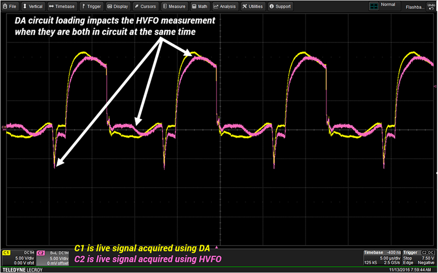
When both probes are connected at the same time, they load each other, resulting in a change in their responses. Note that the negative spikes, which were lower for the HVFO probe when the measurements were made independently, are now comparable in amplitude. The additional loading of the DA has reduced the CMRR of the HVFO probe. In addition, the loading of the circuit by the DA changes the waveshape at the test point, and the HVFO’s measurement echoes that change. In essence, the loading of the DA has been coupled to the HVFO probe results.
The obvious conclusion is that you should not make a measurement with multiple probes connected to the same test point at the same time. If you wish to compare the results of different probes, the best way to proceed is to measure separately, storing acquisitions to an oscilloscope memory. Then, you can recall the memory and compare it to a live acquisition (as we did in Figure 1) or to another memory, without the negative effects of the probes loading each other.
Copyright © 2020-2026 Teledyne LeCroy. All rights reserved. All original content, including text and photos, is the property of Teledyne LeCroy and cannot be reproduced without expressed written permission.
Learn more about the Teledyne LeCroy's optical and other High Voltage probes by visiting this Power Electronics Probes page.

Understanding the internal design of a 10x passive probe reveals the trade-offs that affect signal accuracy, bandwidth, and noise performance.


Knowing a probe’s dynamic range, differential limits, and common-mode voltage helps ensure safe and accurate measurements in high-voltage circuits.

CAT ratings define measurement safety based on source impedance and location—not probe performance or measurement accuracy.

Ground-referenced passive probes can create dangerous short circuits in high-voltage power systems—use properly rated differential probes instead.