On-Die Power Rail Measurements: Setup and Best Practices
Accurate on-die power rail measurements depend on proper sense-line design, differential probing, and careful test setup at the package level.
Accurate on-die power rail measurements depend on proper sense-line design, differential probing, and careful test setup at the package level.

Transmission line losses—driven by skin effect and dielectric properties—play a critical role in degrading high-speed signal integrity and eye performance.
Transmission line loss directly affects eye diagram quality, with around −12 dB at Nyquist marking the limit before signal integrity rapidly degrades without equalization.
Mixed-mode S-parameters are derived from single-ended measurements through matrix transformations that reveal differential and common-mode signal behavior.

We have introduced mixed mode S-parameters and developed a formal structure for handling them. It is now time to discuss converting single-ended S-parameters into mixed-mode S-parameters. This is important because every instrument manufacturer obtains mixed mode S-parameters by first measuring single-ended S-parameters, then converting them mathematically to mixed-mode. This assumes that the interconnects being measured are passive, linear and time invariant. Let’s begin with our model of two transmission lines with crosstalk shown in Figure 1.
Driving the input port differentially means that the differential voltage at the input is:
a1-a3
Similarly, the differential output is:
b2-b4
Remember that these quantities are vectors with magnitude and phase components, and the math operations are vector operations. With the input and output as defined, we are going to calculate the mixed mode S-parameter SDD21—that is, differential in on port 1 and differential out on port 2.
With reference to Figure 1:
SDD21 = 0.5*(S21-S23+S43-S41)
The b2 term is S21-S23. The b4 term is – (-S43 + S41) = S43 – S41. The factor 0.5 is a normalizing factor.
Applying the same technique using the input S-parameters S11, S13, S33 and S31 (not shown in the figure), we can calculate the differential input SDD11:
SDD11 = 0.5*(S11-S13+S33-S31)
The calculation of all the mixed-mode S-parameters from the single-ended S-parameters using vector algebra can be labor intensive. However, doing the calculation with matrices simplifies the process.
Let’s look at the basic calculation of differential signals from single-ended signals in matrix form, as seen in Figure 2. If you’re familiar with matrix math, you can read the differential signal input as a1-a3. Likewise, the differential output is b2-b4. The matrix form is a more concise way of expressing the relationships, and it contains all the possible mixed signal components.
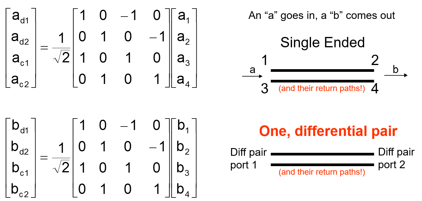
Notice that again, the port assignments are very important. This is the matrix based on the assignments shown in Figure 1; a different port assignment will require a different matrix.
Single-ended S-parameters relate single-ended inputs into single-ended outputs. That statement in matrix notation looks like this:
bs = Ss as
Where:
Likewise, the relationship for the mixed signal inputs and outputs is:
bd = Sd ad
Where:
The goal is to determine the mixed-mode S-parameter matrix from the singled-ended S-parameter matrix.
With some basic matrix math, we can accomplish that as shown in Figure 3.
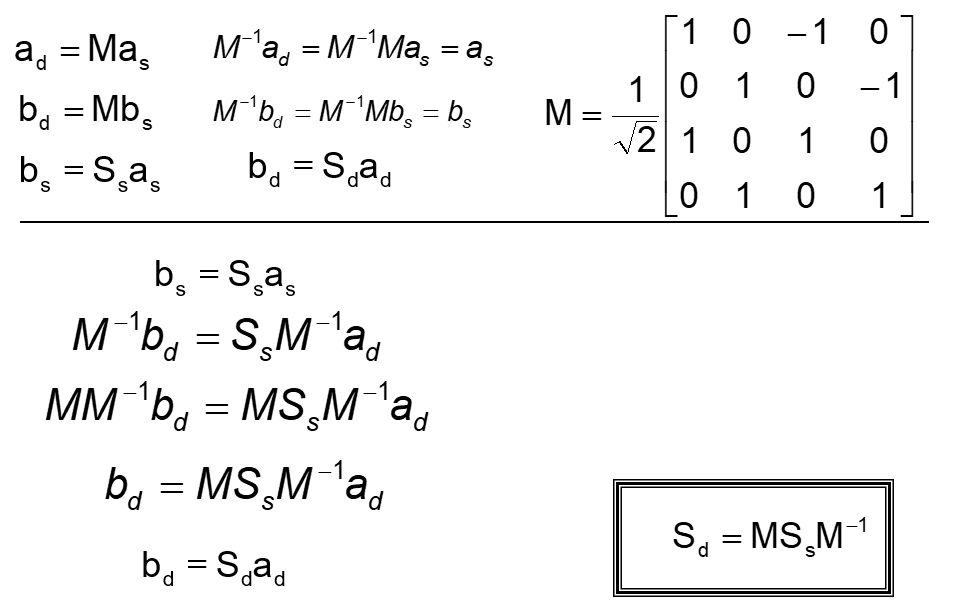
The M matrix is the transform matrix that relates how single-ended vector elements combine to create the mixed-mode elements. M-1 is the inverse of the transform matrix.
Figure 4 shows the detailed solution to deriving mixed-mode S-parameters from the single-ended S-parameters:
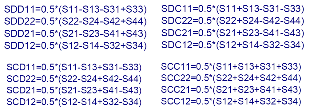
Luckily, if you have a WavePulser 40iX, you do not have to do the math yourself. The instrument does it for you at the touch of a button.
Copyright © 2020-2026 Teledyne LeCroy. All rights reserved. All original content, including text and photos, is the property of Teledyne LeCroy and cannot be reproduced without expressed written permission.

Mixed-mode S-parameters provide a powerful framework for analyzing how differential and common signals interact in complex transmission systems.

Mode conversion in differential signaling is driven by asymmetry between signal paths, revealing itself through mixed-mode S-parameters.

Understand how ripple patterns and resonance effects in S-parameters expose impedance mismatches, interconnect length, and signal integrity behavior.

Understand how return loss and insertion loss interact—and why keeping S11 below −13 dB helps preserve signal integrity in real-world interconnects.